

Introduction
In the previous post, Implementing Over-the-Air Device Firmware Update (OTA DFU) – Part 1, we gave an introduction to over-the-air device firmware update (OTA DFU) and went over the best practices for implementing secure and efficient firmware updates.
In this second post in the series, we'll go over the OTA DFU process used and implemented for nRF52 series chipsets.
We'll cover:
- Introduction to OTA DFU on the nRF52
- nRF52 BLE Secure Bootloader
- DFU Mode
- Firmware Activation
- Bootup Sequence on nRF52
- The Device Firmware Update (DFU) Process
- The nRF DFU BLE GATT Service
- Next Steps: Testing the Nordic Secure Bootloader DFU example
Let's get started!
Introduction to OTA DFU on the nRF52
The nRF SDK provides a few example implementations of bootloaders, each for a different transport (BLE, USB, UART, etc.). The bootloader is used to launch the main application and in some cases switch between multiple applications present in the firmware, and is also used to initialize the device before loading the application.
Here's a diagram showing the architecture of the nRF bootloader modules:
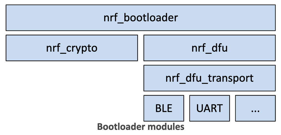
The different modules are:
- nrf_bootloader: the bootloader module which is responsible for activating new firmware, booting into the application, feeding the watchdog, and entering into DFU mode which allows new firmware to be received.
- nrf_crypto: the cryptography library which is responsible for running the cryptographic operations needed for implementing secure firmware updates.
- nrf_dfu: the module that provides Device Firmware Update (DFU) capabilities common across the different supported transport mediums.
- nrf_dfu_transport: the intermediary layer that defines a generic interface that must be implemented by each transport layer.
- The different transport modules that implement the transport-specific operations (BLE, USB, UART, etc.).
nRF BLE Secure Bootloader
The nRF BLE Secure Bootloader implements security measures to protect the DFU process from malicious parties. It uses the Bootloader and DFU modules to implement a bootloader with secure DFU functionality. The bootloader is loaded into a dedicated portion of flash memory separate from the SoftDevice and the Application. It will also live in its own Segger Embedded Studio (SES) project that gets compiled separately and loaded onto the target device.
Keep in mind: the nRF BLE Secure Bootloader depends on the SoftDevice for BLE operation, so the SoftDevice must be present on the device before being to perform a DFU operation.
Here's a detailed diagram showing the locations of the different components in flash memory:
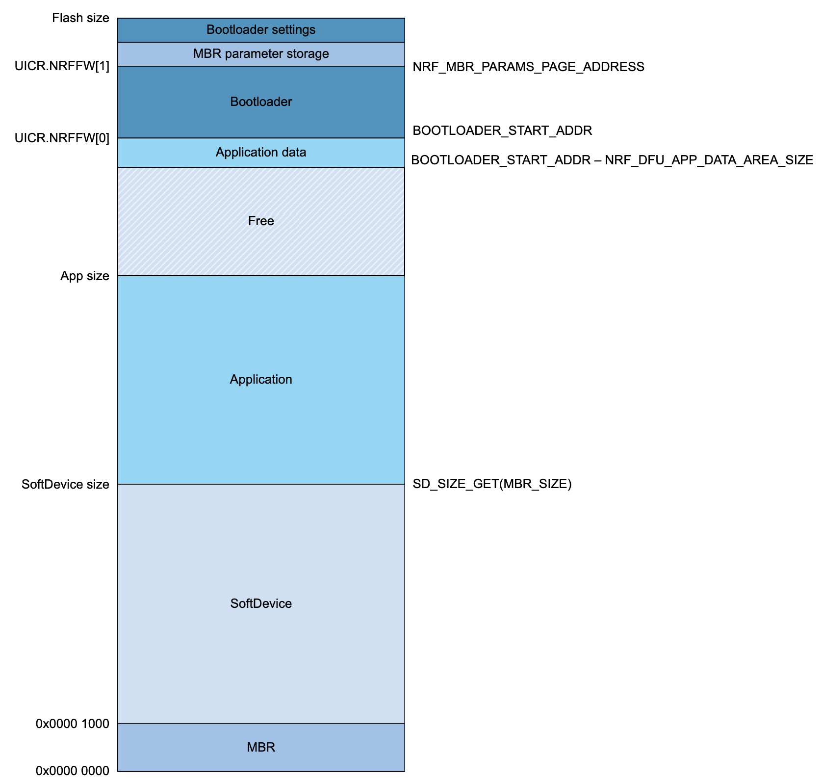
The different sections are:
- DFU Bootloader section:
- Bootloader settings
- MBR parameter storage
- Bootloader
- Application section:
- Application data
- Application
- SoftDevice
- MBR (Master Boot Record)
DFU Mode
When the bootloader is in DFU mode, it activates the DFU BLE transport module and the device is ready to receive new firmware. The bootloader goes into DFU mode if one of the following occurs:
- There is no valid application present in flash memory.
- When a valid SoftDevice and application are present, it is triggered by one of the following:
- A pre-defined button is pressed (defined by NRF_BL_DFU_ENTER_METHOD_BUTTON)
- A pin reset event (defined by NRF_BL_DFU_ENTER_METHOD_PINRESET)
- A special value is present in the GPREGRET register (NRF_BL_DFU_ENTER_METHOD_GPREGRET)
- A request from the application is written to the settings page (NRF_BL_DFU_ENTER_METHOD_BUTTONLESS)
Once DFU mode is entered, an inactivity timer is started. When this timer expires, the bootloader resets. The timer is on any DFU activity.
Firmware Activation
This is the final step of the firmware update process. It is triggered based on the settings stored in the settings section shown above in the memory layout.
It involves either copying the new firmware to replace the old firmware (Single Bank update) or switching to running the new firmware placed in a separate location of the original firmware (Dual Bank update).
Once the new firmware replaces the old firmware, the bootloader settings are updated to allow the new firmware image to boot.
Bootup Sequence
Based on the settings stored in the bootloader settings page, the bootloader determines: whether the application exists, and the location of it. The secure bootloader performs a signature verification of the application before booting into it.
Here are the boot-up steps that occur from reset to starting the application:
- First, the MBR is booted.
- The MBR looks up the location of the bootloader.
- If a bootloader is found, it is run by the MBR.
- A secure bootloader (1) uses cryptographic operations to verify the signature of the firmware (Authenticity) and (2) that is it not corrupted (Data Integrity). This is performed in two scenarios: at bootup, and when a new firmware image is received.
- If a bootloader is not found, the MBR boots the image that follows it (the MBR) at address 0x1000 (the SoftDevice).
- The SoftDevice then boots the application.
There are four different boot validation modes that can be configured.
- Signature validation (ECDSA) - most secure, and data integrity check.
- Hash validation (SHA-256) - less security, and data integrity check.
- CRC validation (CRC32) - no security, only data integrity check.
- No validation - no security, no integrity check.
This is configured as part of the firmware update package. If a signature mode is specified, then the signature will exist in the package. For hash and CRC validation, the cryptographic digest is created on-chip and written to flash when the update is applied.
Important Note: the boot validation is independent of the firmware update validation process. This means that the update package is signed regardless of the secure boot mode contained in it. This ensures that the system is protected from unauthorized firmware updates even with no boot validation.
The Device Firmware Update (DFU) Process
The DFU process can be run by using one of the following Nordic tools. Each of these tools is used to send the DFU package to the target device to perform the update.
- The
nrfutilcommand-line tool - nRF Connect for desktop
- nRF Connect for mobile
Two devices are involved in the DFU process: the DFU controller which transfers the DFU package, and the DFU target which receives and applies the DFU package.
Here's the diagram that we looked at in the previous post, which shows the workflow of the DFU process:

The nrfutil command-line tool is used to generate the DFU package that gets transferred by the DFU controller to the DFU target. The update package contains:
- The init packet
- The binary data (any combination of Bootloader + SoftDevice + Application)
Here are the basic steps involved in the DFU process:
- The init packet gets transferred to the DFU target first.
- The target then validates the init packet.
- If the init packet is successfully validated, the DFU controller then transfers the binary data.
- The target then post-validates the binary data.
- If the target validates the binary successfully, it then resets.
- After reset, the bootloader activates the new firmware image.
The DFU package will contain two updates if both the SoftDevice and Application are to be updated. The process is seamless to the end-user and is perceived as a single update (even though in reality it is two updates).
The Init Packet
The manifest portion of the DFU image (referred to as the init packet in nRF terminology) must be signed to protect against malicious parties attempting to impersonate the authentic author of the DFU image.
The secure bootloader uses the cryptography library (nrf_crypto) to perform the different necessary cryptographic operations to validate the init packet. Different backends are available for use in the bootloader (we'll be using the micro-ecc backend, which is an open-source third-party library available on GitHub).
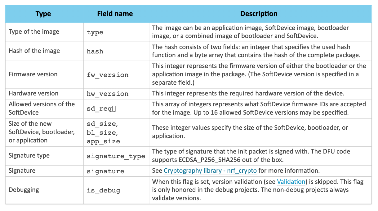
The init packet contains different fields that describe the contents of the DFU package. Here's a table (taken from Nordic's documentation) that shows all the fields within the init packet:
In addition to validation of the signature, the init packet is also verified to make sure that it is compatible with the device and the current firmware and hardware. The different steps of the validation process are performed in the following order:
- Signature of the packet,
signature.
To be able to verify the signature, the validation code needs the public key that corresponds to the private key that was used to sign the init packet.
This key is located in the filedfu_public_key.c. - Firmware type,
fw_type. - Hardware version,
hw_version. - SoftDevice version,
sd_req. - Firmware version,
fw_version. - Firmware size to see whether the update will fit.
The signature is generated using a private key that you create using the nrfutil command-line tool (before creating the DFU package). This private key needs to be protected and kept a secret from malicious parties.
The bootloader contains a copy of the public key only, which is used to verify the signature created by the associated private key.
nRF DFU BLE GATT Service
The GATT Service implemented as part of the Nordic Secure DFU module is referred to as the Secure DFU Service. It is a 16-bit UUID registered with the Bluetooth SIG with the value 0xFE59. It's a standalone primary service that does not depend on any other services. This is implemented on the DFU target side (GATT Server) and exposed to the DFU controller (GATT Client).
It contains the following Characteristics:
- DFU Control Point
UUID: 0x8EC90001-F315-4F60-9FB8-838830DAEA50
Permissions: Write, Notify - DFU Packet
UUID: 0x8EC90002-F315-4F60-9FB8-838830DAEA50
Permissions: Write Without Response, Notify
Security requirements (encryption) are not required for the service, however, its implementation is recommended to provide higher security.
DFU Control Point Characteristic
The DFU Control Point characteristic is used to control the state of the DFU process. DFU operations are initiated by writing to this characteristic.
At the end of the DFU process, a notification is sent back to the DFU controller to report the status of the update. The DFU controller is responsible for keeping track of the update progress.
DFU Packet Characteristic
The DFU Packet characteristic is used to transfer the DFU data from the DFU controller to the DFU target.
DFU Init Packet Transfer
First, the init packet is sent to the DFU target. Once it's been verified to be transferred successfully, the DFU controller will issue a command to initiate the validation of the init packet.
DFU Data Transfer
Once the init packet has been successfully validated, the firmware image is split up into several chunks to be transferred to the DFU target. If the transfer operation is suspended at any point (e.g. due to a power failure), the DFU process is able to continue from the last valid data chunk that was received.
Once all the data chunks have been transferred successfully, the DFU controller will issue a CRC check command to verify the integrity of the data. If the CRC check passes, the DFU controller will then issue a command to trigger the actual firmware update.
Buttonless DFU
The BLE Secure DFU Bootloader example included in the SDK relies on pressing a button (Button 4 on the nRF52840 DK) during bootup to go into DFU mode and be able to start the OTA DFU process.
In production and in practice, however, a "Buttonless DFU" probably makes more sense. This allows you to expose the DFU GATT Service alongside your application's GATT Services and be able to go into DFU mode from within the Application running on your device.
Next Steps: Testing the Nordic Secure Bootloader DFU example
In the next post in this series, we'll go through testing Nordic's OTA DFU example on the nRF52840 dev board and guide you through doing the same step-by-step.
If you're interested in learning about over-the-air device firmware update in much more detail including implementing it for your nRF52 project in full detail, then check out the Bluetooth Developer Academy where I cover this topic in a full course.
The course includes implementing Buttonless DFU, which integrates DFU into your application and allows triggering DFU mode by a remote BLE Client instead requiring to be triggered manually on the end-device.
Summary & Closing
In this post, we covered:
- What is Device Firmware Update (DFU)?
- What is Over-the-Air Device Firmware Update (OTA DFU)?
- How does OTA DFU work?
- The role of the bootloader
- The basic steps of OTA DFU


